โปรดเลือกที่อยู่การจัดส่ง

การเลือก ประเทศ/ภูมิภาค อาจส่งผลต่อปัจจัยต่างๆ เช่น ราคา ตัวเลือกการจัดส่งและความพร้อมจำหน่ายสินค้า
ผู้ติดต่อของฉัน
IGUS MOTION PLASTICS (THAILAND) CO., LTD.

1340 Soi Bangkok-Nonthaburi 30, Bangkok-Nonthaburi Rd.,

Bangsue, Bangsue

Bangkok 10800 Thailand

+66 (0)2 587 4899
+66 (0)2 587 4898
TH(TH)

drylin® T - System design, vertical, 1 rail and 1 carriage

2nd Step:

Check whether the clearances of the aggressive forces lie within the permitted values (see Maximum permitted clearances).

Maximum permitted clearances:

Option: 1 rail, 1 carriage
sy + sz < 2 Lx - Y0
ay + az < 2 Lx - Y0
sy < 5 Zm
sz < 5 Zm

3rd Step:

Calculate the required driving power

Initially four calculations should be carried out:
The driving power Fa corresponds to the calculated maximum value:


4th Step:

Calculate the maximum bearing load

4.1

Maximum bearing load in y-direction

4.2

Maximum bearing load in z-direction
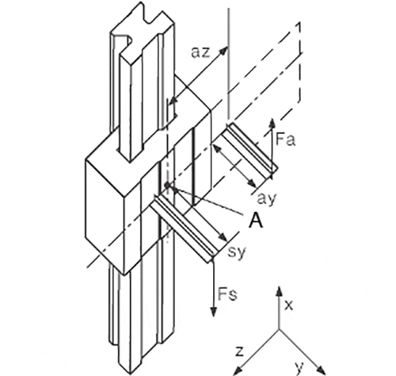
A = Point of origin


Variables in the calculation:

Fa: Driving power [N]
Fs: Mass force [N]
Fy, Fz: Bearing load in y- or z-direction [N]
sx, sy, sz: Clearance of the mass force
in x-, y- or z-direction
[mm]
ay, az: Clearance of the driving power
in y- or z-direction
[mm]
wx: Clearance of the carriage on a rail [mm]
LX: Constant based on the installation size [mm]
Zm: Constant based on the installation size [mm]
Y0: Constant based on the installation size [mm]
b: Clearance of the guide rails [mm]
µ: Coefficient of friction,
µ = 0 in static loads,
µ = 0.2 in dynamic loads
 
ZW: Number of carriages per rail  


The constant values:

Order no. LX ZM Y0
  [mm] [mm] [mm]
TW-01-15 29 16 11,5
TW-01-20 35 23 15,0
TW-01-25 41 25 19,0
TW-01-30 49 29 21,5


Coefficients:

  1 rail,
1 carriages
K1 |(ay+Y0)/Lx|
K2 (sy+Y0)/Lx
K3 |az/Lx|
K4 |sx/Lx|
K5 sz/Lx
K6 |(sy+Y0)/Zm|
K7 |sz/Zm|

5th Step:

Check the maximum bearing load of the most strongly stressed bearing with the calculated load in Step No. 4.

Maximum permitted load:

Order no. Fymax, Fzmax
[N]
TW-01-15 2000
TW-01-20 3700
TW-01-25 5000
TW-01-30 7000

6th Step:

Determination of the maximum permitted speed for the load in Step No. 4
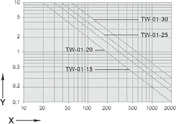
Diagram for the determination of the maximum permitted speed for the determined bearing load.
X = centric bearing load [N]
Y = permitted mean velocity [m/s]


เงื่อนไข "Apiro", "AutoChain", "CFRIP", "chainflex", "chainge", "รางสำหรับเครน", "ConProtect", "cradle-chain", " ;CTD", "drygear", "drylin", "dryspin", "dry-tech", "dryway", "รางแบบง่าย", "e-chain®", " ระบบ e-chain® ", "e-ketten", "e-kettensysteme", "e-loop", "energy chain", " ระบบ energy chain ", "Enjoyneering", "e-skin", "e-spool", "fixflex", "flizz", "i.Cee", "ibow", "igear" , "iglidur", "igubal", "igumid", "igus", "igus พัฒนาการเคลื่อนที่", "igus:bike", "igusGO", "igutex", "iguverse" , "iguversum", "kineKIT", "kopla", "manus", "motion plastics", "motion polymers", "motionary", "พลาสติกเพื่ออายุการใช้งานที่ยาวนานขึ้น", "print2mold" , "Rawbot", "RBTX", "readycable", "readychain", "ReBeL", "ReCyycle", "reguse", "robolink", "Rohbot", "savfe" , "speedigus", "superwise", "ใช้งานแบบแห้ง", "tribofilament", "triflex", "twisterchain", "เมื่อมันเคลื่อนที่ igus จะพัฒนา", "xirodur", " Xiros " และ "ใช่" เป็นเครื่องหมายการค้าที่ได้รับการคุ้มครองตามกฎหมายของ igus® GmbH/ Cologne ในสหพันธ์สาธารณรัฐเยอรมนี และในกรณีที่มีผลบังคับใช้ในต่างประเทศบางประเทศ นี่เป็นรายการเครื่องหมายการค้าโดยย่อ (เช่น อยู่ระหว่างดำเนินการยื่นขอเครื่องหมายการค้าหรือเครื่องหมายการค้าจดทะเบียน) ของ igus® GmbH หรือบริษัทในเครือของ igus® ในเยอรมนี สหภาพยุโรป สหรัฐอเมริกา และ/หรือประเทศหรือเขตอำนาจศาลอื่นๆ

igus® GmbH ไม่ได้จำหน่ายผลิตภัณฑ์ใดๆ ของบริษัท Allen Bradley, B&R, Baumüller, Beckhoff, Lahr, Control Techniques, Danaher Motion, ELAU, FAGOR, FANUC, Festo, Heidenhain, Jetter, Lenze, LinMot, LTi DRiVES, Mitsubishi, NUM, Parker, Bosch Rexroth, SEW, Siemens, Stöber และผู้ผลิตไดร์ฟอื่น ๆ ทั้งหมดที่ระบุไว้ในเว็บไซต์นี้ ผลิตภัณฑ์ที่นำเสนอโดย igus® เป็นของบริษัท igus® GmbH